
10 Slicer Settings That Instantly Improve Print Quality

Bad prints usually come from a few overlooked slicer settings. Learn which adjustments actually matter, why they work, and which ones to change first today.
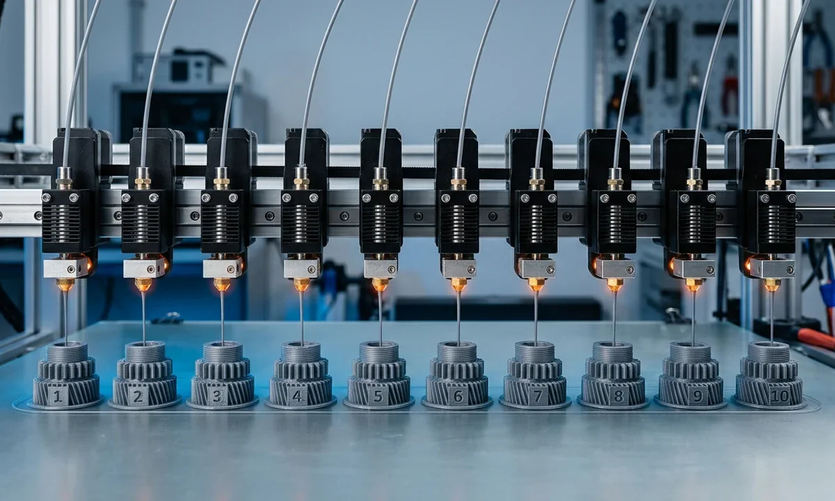
Eight hours into a helmet print, the outer shell still looked rough. Ringing showed up near sharp corners, the first layer bulged outward, and thin strings stretched between vent openings. Most FDM printers can produce cleaner results than that without changing a single hardware component. Start with practical baseline settings instead: 0.2 mm layer height, 45 mm/s outer wall speed, 100% PLA cooling, and a carefully tuned first layer. Those four adjustments alone solve a surprising number of visible defects.
The largest print-quality gains usually come from slicer decisions controlling extrusion timing, cooling behavior, and movement accuracy. Cura, PrusaSlicer, Orca Slicer, and Bambu Studio all expose these controls differently, though the mechanical principles stay the same. A CoreXY machine running rigid linear rails reacts differently than a lightweight bedslinger, especially once acceleration rises above 5000 mm/s².
The table below works as a starting reference, not a universal preset.
| Setting | Starting Range | Lower Values Cause | Higher Values Cause | Notes |
|---|---|---|---|---|
| Layer Height | 0.12-0.2 mm | Longer prints | Rougher surfaces | Smaller nozzles favor thinner layers |
| Outer Wall Speed | 35-60 mm/s | Heat buildup | Ringing and ghosting | CoreXY printers tolerate faster speeds |
| Retraction Distance | 0.5-1 mm direct drive | Stringing | Clogs and grinding | Bowden systems need more travel |
| Fan Speed PLA | 70-100% | Sagging bridges | Weak layer bonding | PETG needs less cooling |
| Bed Temperature PLA | 55-65C | Poor adhesion | Elephant Foot | Textured PEI may need less heat |
Tune Settings Systematically
Five uncontrolled changes can hide the real source of a print defect for days. A warped corner might come from excessive cooling, poor Z-offset, an overheated bed, or simply printing too fast for the machine's motion system. Change one variable at a time using a repeatable calibration part that finishes in under 20 minutes. Small tower tests reveal problems quickly.
- Start with first-layer reliability before cosmetic tuning
- Save separate profiles for PLA, PETG, and ABS instead of chasing universal values
- Outer wall quality reveals problems faster than infill
- Modern slicers allow per-feature speeds and cooling settings that reduce compromise
Most experienced operators tune foundational settings first because those values influence nearly every other parameter downstream. Layer height affects extrusion pressure. Print speed changes cooling time. Z-offset alters how the nozzle loads the first layer against the bed surface. Watch out for tuning retraction before stabilizing temperature because hot filament strings differently than cooler material, even with identical travel moves.
Motion limits matter more now than they did five years ago. A Bambu Lab X1C or tuned Voron 2.4 can hold clean corners at 150 mm/s because input shaping compensates for resonance and the frame stays rigid under acceleration. Older Cartesian machines with heavy moving beds often lose positional accuracy above 70 mm/s, especially during rapid direction changes. Perimeter Speed settings help here. Slow only the visible outer walls first and leave infill faster.
Cooling also interacts directly with geometry. Bridges collapse when layers stay soft too long. Overcooled PETG loses interlayer strength and splits under load because the material never achieves proper thermoplastic welding between passes.
1Layer Height
Why Surface Finish Changes
- Layer Height controls vertical resolution and visible layer lines across the entire model
- Recommended range: 0.1-0.15 mm for high-detail parts, 0.2 mm for general printing, 0.28-0.32 mm for fast prototypes
- Lower values dramatically improve top surfaces and curved geometry
- Extremely low heights below 0.1 mm often create diminishing returns while doubling print time
Every FDM print carries a visible staircase pattern along curved surfaces. Layer height determines how obvious that texture becomes because each deposited pass forms a physical step. A dragon model printed at 0.12 mm usually looks smoother around horns and scales than the same file printed at 0.28 mm, even before sanding or primer.
Most users settle near 0.2 mm for everyday printing because it balances detail, speed, and extrusion stability. Smaller nozzles, especially 0.25 mm setups, gain more visible improvement from thin layers because the extrusion path itself already supports fine detail. Larger 0.6 mm nozzles behave differently. Thick layers between 0.3 and 0.4 mm often produce stronger workshop parts while cutting print time dramatically.
Watch out for chasing ultra-fine settings below 0.08 mm on standard consumer hardware. Print times explode, nozzle contamination becomes more visible, and Incorrect Retraction Distance problems suddenly stand out on glossy surfaces.
2Print Speed
The Motion Quality Balance
- Print Speed controls how quickly plastic is deposited and how much time layers have to cool
- Start around 40-60 mm/s for quality-focused printing on most machines
- Modern CoreXY printers can often maintain quality between 100-200 mm/s with tuned acceleration
- Excessively slow speeds can cause heat creep and over-softened layers on some hotends
A fast printer does not automatically produce fast high-quality prints. Motion speed changes nozzle pressure, cooling time, resonance behavior, and corner accuracy simultaneously. Ghosting near embossed text often appears because the frame keeps vibrating after a rapid direction change. Bedslinger machines exaggerate that effect since the moving bed carries significant mass during acceleration.
Rigid CoreXY systems handle speed more cleanly because the gantry moves less weight. In our testing on a Voron 2.4 and Bambu P1P, clean PLA walls stayed achievable around 140 mm/s once acceleration and cooling matched the material. An Ender 3 running stock wheels needed far slower Perimeter Speed values, closer to 45 mm/s, before ringing disappeared from sharp corners.
Slow only the visible surfaces first. Most slicers separate outer walls, infill, bridges, and First Layer movement speeds. That single adjustment usually improves cosmetic quality faster than globally reducing every motion parameter.
3Retraction Distance
Stopping Stringing Effectively
- Retraction Distance pulls filament backward during travel moves to reduce oozing between features
- Direct drive systems usually need 0.5-1.0 mm while Bowden setups often require 3-6 mm
- Proper tuning reduces stringing and blobs around detailed models
- Excessive retraction can grind filament or trigger clogs with flexible materials
Molten plastic keeps flowing briefly after extrusion stops because pressure remains trapped inside the hotend. Retraction relieves part of that pressure before the nozzle travels across open space. Without it, fine hairs form between model features and small blobs accumulate around seams.
Bowden printers require longer retraction because the PTFE tube compresses under load. The extruder motor may move several millimeters before the nozzle actually stops oozing. Direct drive systems respond much faster since the drive gears sit close to the melt zone. A tuned Sprite Extruder or Bambu direct drive setup often prints clean PLA at 0.8 mm retraction or less.
Watch out for aggressive settings with TPU. Flexible filament compresses inside the path instead of retracting cleanly, then jams near the heat break. Excessive retraction also increases clog risk with abrasive composites containing carbon fiber or glow additives because repeated movement grinds particles into the nozzle interior.
4Infill Density
Strength Versus Waste
- Infill Density controls how much internal structure supports the model
- Use 15-20% for decorative prints, 40-60% for functional parts, and 80-100% only for maximum rigidity
- Higher density increases weight, strength, and print time simultaneously
- Most parts gain surprisingly little extra strength above roughly 60% density
Dense infill looks reassuring in slicer previews, but walls usually contribute more real strength than packed interiors. Stress concentrates near outer surfaces where bending and impact forces act most aggressively. A bracket with four solid perimeters and 35% gyroid often survives longer than a thin-walled print stuffed with 80% grid infill.
Pattern choice changes behavior too. Gyroid became popular because the continuous curves distribute force evenly while reducing abrupt toolpath changes that shake the printer. Honeycomb still works well for compressive loads, though it prints slower because the nozzle constantly changes direction. Grid patterns print quickly but can create nozzle collisions where lines cross on the same layer.
Reserve extremely high infill for threaded parts, clamps, or heavily loaded mounts. Decorative helmets, statues, and cosplay props rarely benefit from dense interiors. They only consume more filament and increase print time. Large solid sections also trap heat longer, which sometimes softens upper layers during tall PLA prints.
5Wall Count
Perimeters Build Real Strength
- Wall Count sets the number of outer perimeter loops surrounding the print
- Decorative models usually print well with 2-3 walls while functional parts benefit from 4-5
- Additional walls improve surface consistency and mechanical durability
- Thin features can become overfilled if wall counts exceed available geometry width
Outer shells absorb most mechanical stress during real use. Drop a printed bracket on concrete and the failure almost always begins near the perimeter, not deep inside the infill structure. Extra walls strengthen those load paths directly while also improving surface consistency on visible faces.
Different slicers label the setting differently. Cura uses Wall Line Count, while PrusaSlicer, Orca Slicer, and Bambu Studio typically call them Perimeters. The mechanical effect stays identical: more loops create thicker shells. A 0.4 mm nozzle printing four perimeters produces roughly 1.6 mm of shell thickness before infill even begins.
Increase wall count before cranking infill higher. Functional PETG hinges, tool holders, and battery mounts usually benefit more from extra shells than from dense internal structure. Watch out for narrow geometry, though. Thin sword blades or miniature details can overfill quickly if the slicer tries squeezing too many walls into limited space, especially after increasing Extrusion Width beyond nozzle diameter.
6Fan Speed
Cooling Changes Everything
- Fan Speed controls how quickly freshly extruded filament solidifies after deposition
- PLA overhangs and bridges often need 100% cooling for clean detail
- PETG usually performs best around 0-30% because excessive cooling weakens bonding
- ABS, ASA, and nylon generally print with the fan disabled to prevent cracking and warping
Cooling controls shape retention during the few critical seconds after extrusion. PLA bridges sag dramatically if layers stay soft too long because gravity pulls the material downward before it hardens. Strong Part Cooling fixes that by freezing unsupported sections quickly enough to preserve sharp edges and cleaner overhangs.
Engineering plastics react differently. ABS and ASA shrink aggressively while cooling, so heavy fan use increases internal stress and causes corner lifting or layer cracks. We saw this repeatedly on open-frame machines printing large ABS enclosures. Turning the fan off and adding a basic enclosure stabilized temperatures immediately. PETG falls somewhere between the two extremes. Moderate airflow improves overhangs, but excessive cooling weakens layer adhesion and creates brittle surfaces.
Speed changes cooling requirements too. A fast CoreXY machine may outrun the fan's ability to solidify tiny layers, even at maximum airflow. Slow the print slightly if bridges curl upward or nozzle scars appear across small features. Cooling alone cannot compensate for excessive motion speed.
7Bed Temperature
First Layer Stability
- Bed Temperature controls first-layer adhesion and thermal stability during the print
- PLA commonly runs between 55-65C, PETG between 70-85C, and ABS around 100-110C
- Proper temperatures reduce corner lifting and uneven shrinkage
- Excessive heat can create elephant's foot and distort bottom dimensions
The first layer locks the entire print to the build surface while internal stress starts building above it. Bed heat slows thermal contraction during those early layers, which reduces warping and keeps corners attached. PLA generally prints reliably around 60C on textured PEI, while ABS often needs over 100C plus an enclosure before large parts stay flat.
Different surfaces change the equation. Smooth PEI grips aggressively once warm, sometimes enough to print PLA several degrees cooler. Glass behaves differently because it releases heat more slowly and usually needs slightly higher temperatures for reliable adhesion. Ambient conditions matter too. A printer sitting near an open window can warp PETG prints even with otherwise correct bed settings.
Watch for Elephant Foot along the bottom edge. Excessive bed heat softens the lower layers so much that nozzle pressure squashes them outward during the next passes. Lower the bed temperature slightly or reduce initial layer squish if bottom dimensions consistently measure oversized.
8Support Type
Cleaner Overhang Strategy
- Support Type determines how overhangs are held during printing and how easily supports detach afterward
- Tree or organic supports excel on statues, miniatures, and curved geometry
- Linear supports remain faster and more predictable for flat mechanical overhangs
- Organic supports often reduce scarring but can increase slicing time and travel complexity
Support settings directly affect the finish quality of downward-facing surfaces. Dense contact layers hold overhangs securely but often leave rough scars once removed. Loose supports detach more cleanly, though unsupported sections may droop during printing. You see this tradeoff immediately on figurines with curved armor or detailed facial features.
Modern slicers improved support generation dramatically during the last few years. Cura tree supports, Prusa organic supports, and Orca adaptive branches all reduce material use while reaching awkward geometry more efficiently. Those branching structures also leave more open airflow around the model, which helps cooling on steep overhangs. Mechanical parts still favor traditional linear supports in many cases because flat contact surfaces print faster and predictably.
Choose supports based on geometry, not habit. A gearbox housing with square recesses usually prints best using standard block supports and a conservative Support Angle threshold. Organic structures shine on helmets, miniatures, and statues where curved surfaces dominate the model shape.
9Line Width
Extrusion Width Control
- Line Width determines how wide each deposited extrusion path becomes relative to nozzle size
- Most printers perform best between 100-120% of nozzle diameter
- Slightly wider lines improve wall bonding and reduce perimeter gaps
- Widths above 150% can create rough surfaces and uneven extrusion behaviour
Extruded filament behaves more like flattened rope than a perfect cylinder. Line Width controls how much the slicer spreads each deposited path across the layer below. Wider extrusion paths bond aggressively because neighboring lines overlap more thoroughly, which improves strength and reduces tiny wall gaps.
A standard 0.4 mm nozzle often prints beautifully around 0.42 to 0.48 mm width. Functional parts printed with a 0.6 mm nozzle benefit even more from wider settings because thicker extrusion paths increase shell strength quickly while shortening print times. We tested several PETG tool mounts at 0.72 mm width on a 0.6 nozzle and saw noticeably stronger layer bonding compared with narrow extrusion paths.
Treat this as a refinement setting. Temperature stability, flow calibration, and motion tuning matter far more during early troubleshooting. Excessively wide extrusion creates rough surfaces, dimensional inaccuracies, and corner buildup where the nozzle struggles to compress too much material into tight geometry.
10Z-Offset
Perfecting The First Layer
- Z-Offset fine-tunes the nozzle distance from the build plate during the first layer
- Ideal spacing lightly squishes filament without scraping the surface
- Typical adjustments fall around -0.1 to -0.3 mm from mesh zero depending on setup
- Incorrect offsets cause nozzle dragging, poor adhesion, or visibly separated first-layer lines
A flawless first layer depends more on nozzle spacing than almost any other calibration variable. The nozzle must press filament firmly enough to anchor the print while still allowing material to flow outward smoothly. Even expensive automatic leveling systems still require manual Z-Offset tuning because nozzle wear, plate coatings, and filament types change the ideal gap constantly.
Visual cues reveal problems quickly. Lines printed too high look rounded and separated, with visible gaps between adjacent passes. Excessively low offsets scrape the build plate, produce rough textures, and force material outward into ridges. The first layer should appear smooth and slightly compressed without becoming glossy or transparent.
Watch out for changing build surfaces without recalibrating. Textured PEI, smooth PEI, garolite, and glass all position the nozzle differently relative to the probe measurement. A change that takes two minutes now can prevent a failed ten-hour print later.
Highest Impact Changes
Most visible print defects trace back to four or five settings, not fifty. Beginners often waste time adjusting obscure acceleration filters while the nozzle still sits too high above the bed or the filament cools incorrectly for the material. Prioritize settings based on visible impact first, then refine smaller details once the foundation stays consistent across multiple prints.
- Start first with Z-offset and bed temperature because failed first layers ruin every print
- Adjust layer height and print speed next because they define overall visual quality
- Tune retraction and cooling once extrusion and motion are consistent
- Refine line width, wall count, and support behaviour later for specialised jobs
Several settings must be evaluated together instead of independently. Print Speed and Part Cooling interact constantly during bridges and overhangs. Fast movement reduces the time each layer has to solidify, which means a PLA bridge that succeeds at 45 mm/s may sag badly at 120 mm/s even with identical fan settings. Wall Count and Line Width also combine into total shell thickness. Increasing both simultaneously can strengthen parts quickly, though narrow geometry may overfill.
Retraction tuning depends heavily on nozzle temperature and travel behavior. Hot PETG strings aggressively even with ideal retraction because the material stays fluid longer during travel moves. Save multiple slicer profiles instead of chasing one universal preset. A fast PETG workshop profile rarely produces the same cosmetic finish as a slower PLA display setup tuned for detail.
Dial In Better Prints
Most FDM quality problems come from controllable slicer behavior, not from cheap hardware. First-layer spacing, cooling balance, extrusion timing, and motion speed determine the majority of visible defects long before frame upgrades or expensive hotends enter the picture. A carefully tuned mid-range printer regularly outperforms poorly calibrated premium machines.
Focus on consistency first. Reliable adhesion and clean outer walls matter far more than chasing 0.08 mm layers during early learning. Once those basics stay stable across repeated prints, start refining advanced settings such as Support Angle thresholds, adaptive Line Width, or material-specific cooling curves. Small controlled adjustments teach more than downloading ten random community profiles.
Keep the tuning process narrow. Duplicate an existing slicer profile, print a short calibration model, then change only one variable before testing again. That method feels slow during the first few sessions, though it prevents confusion later when multiple settings interact unexpectedly. Building separate profiles for PLA display models, PETG functional parts, and ABS enclosure work usually improves print quality faster than endless experimentation inside a single preset.
Technical communicator specialising in 3D printing workflows, covering the full content spectrum: foundational guides, step-by-step how-to tutorials, hands-on reviews, curated top picks, troubleshooting solutions, and industry news.