
DMLS vs SLM: Understanding the Differences in Metal 3D Printing

Curious about Dmls vs Slm and why manufacturers debate them constantly? This guide breaks down Slm vs Dmls processes, materials, and real-world applications. Read before choosing a system.
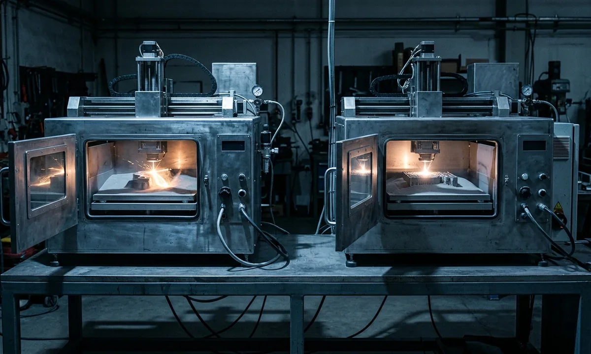
A titanium aerospace bracket printed on an EOS system and a similar bracket printed on a Concept Laser machine can leave the build chamber with nearly identical geometry, density, and tensile strength. Yet one vendor may describe the process as Direct Metal Laser Sintering, while another calls it Selective Laser Melting. That naming overlap confuses buyers, especially teams comparing qualification standards, powder behavior, and long term production costs.
DMLS usually describes a laser powder bed fusion process that sinters or partially melts fine metal powder layers. SLM typically refers to systems that fully melt the powder into a near fully dense structure. In practice, modern systems from both categories often reach densities above 99 percent, which explains why the terminology keeps blurring.
Aerospace and medical manufacturers still care about the distinction because process parameters influence microstructure, residual stress, roughness, and certification workflows. A turbine component designed for repeated thermal cycling faces different risks than a surgical guide or conformal cooling insert.
Laser powder bed fusion, often shortened to LPBF, spreads thin metal powder layers across a build plate and fuses them with a high energy laser. Layer thickness, model orientation, powder spreading quality, and thermal management all shape the final part.
Dmls vs SlmDMLS Under the Microscope
Most DMLS systems build parts with powder layers between 20 and 60 microns thick. A recoater blade or roller spreads each layer across the build plate, then a fiber laser scans selected regions based on sliced CAD data. The machine repeats that cycle hundreds or thousands of times until the component reaches full height.
EOS helped popularize DMLS in industrial manufacturing, particularly for cobalt chrome, aluminum, maraging steel, Inconel, and titanium alloys. Materials with broad processing windows generally perform better because the process depends on controlled thermal gradients rather than aggressive overheating. Operators constantly monitor material flow and powder spreading consistency because uneven layers create void formation and dimensional drift.
The term "sintering" creates confusion. Early DMLS systems often fused particles without fully liquefying every region. Modern industrial platforms operate much closer to complete melting, especially in aerospace grade titanium and nickel superalloys. Even so, manufacturers still use the DMLS label for historical and branding reasons.
Support structures matter. Metal powder cannot hold unsupported overhangs the way polymer powder beds sometimes can. Engineers add supports to anchor parts thermally and mechanically, reduce warping, and channel heat into the build plate. Removing those supports later requires machining, EDM cutting, or manual finishing.
Porosity remains one of the main operational concerns. Gas entrapment, unstable melt pools, contamination, or incorrect laser settings can reduce density and weaken fatigue performance. Hot isostatic pressing often follows printing for mission critical aerospace parts because it compresses internal pores under heat and pressure.
Surface finish also limits direct part usability. As printed DMLS components commonly show roughness values between Ra 6 and Ra 15 microns, depending on alloy and orientation. Manufacturers usually add machining, bead blasting, polishing, or heat treatment before final deployment.
Compared with subtractive manufacturing, DMLS wastes less raw material when producing lattice structures or complex cooling channels. Build speed, however, stays relatively slow. A dense steel component may require twenty hours or more inside the machine before post processing even begins.
Dmls vs SlmSLM Beyond the Buzzword
High performance turbine housings often reveal why SLM gained traction in aerospace programs. Engineers wanted metal parts with densities approaching wrought material, predictable grain structures, and stronger fatigue resistance under cyclic loading. Full powder melting gave machine builders a path toward those targets.
SLM systems spread thin metallic powder layers across a heated build platform, then drive a high power laser through selected regions until the particles liquefy completely. The molten pool rapidly solidifies into dense metal. Layer thickness commonly falls between 20 and 50 microns, though some aluminum systems print thicker layers to increase throughput.
Concept Laser, SLM Solutions, and several newer Chinese manufacturers built their reputations around this approach. Stainless steel 316L, Ti6Al4V titanium, aluminum AlSi10Mg, and Inconel 718 remain common choices because they respond predictably to intense thermal cycling. Crack sensitive alloys create problems. Some copper and high carbon steels still require narrow processing windows or modified scan strategies.
Mechanical performance drives most SLM purchasing decisions. Properly tuned systems routinely achieve densities above 99.5 percent, and tensile properties can rival forged material after heat treatment. Medical implant producers value that consistency because pore defects and incomplete fusion can compromise long term reliability inside the body.
Thermal stress creates tradeoffs. Fully melting the powder generates steep temperature gradients, which increases distortion risk and demands careful support placement. Large flat geometries frequently curl upward during printing if operators mismanage scan patterns or build plate temperature.
Surface quality remains imperfect. SLM parts generally require machining, polishing, or abrasive finishing before sealing surfaces or threaded features meet production standards. Powder removal also becomes harder inside narrow channels because partially sintered residue can accumulate in internal cavities.
Production economics complicate the picture further. Multi laser SLM systems print faster than older single laser platforms, but they consume substantial electrical power and require tightly controlled inert gas environments. Industrial buyers usually compare SLM not only against DMLS, but also against DED systems and precision CNC workflows before approving capital investment.
Dmls vs SlmSide-by-Side Process Breakdown
Procurement teams often discover that modern LPBF platforms overlap far more than vendor brochures suggest. A machine marketed as DMLS may fully melt titanium powder during one build while operating closer to partial fusion with another alloy. Meanwhile, many SLM systems adjust laser exposure dynamically to avoid overheating thin walls or fragile lattice sections.
The practical distinction comes from thermal strategy and process tuning rather than a universal engineering standard. DMLS historically emphasized controlled sintering and broad alloy compatibility. SLM focused on complete melting to maximize density and mechanical consistency. Current industrial systems blur those boundaries because manufacturers optimize scan paths, beam shaping, and powder handling differently.
The following comparison outlines where meaningful differences still appear in production environments.
| Category | DMLS | SLM |
|---|---|---|
| Core mechanism | Partial to near complete fusion of metal powder | Full melting of powder into dense melt pool |
| Typical density | 97% to 99.5% | 99% to 99.9% |
| Layer thickness | 20 to 60 microns | 20 to 50 microns |
| Surface roughness | Ra 6 to 15 microns | Ra 5 to 12 microns |
| Material flexibility | Broad alloy range, including crack sensitive metals | Best with highly process stable alloys |
| Thermal stress | Moderate to high | High |
| Support dependence | Significant | Very significant for large geometries |
| Post processing | Heat treatment, machining, HIP for critical parts | Similar requirements, often stricter distortion control |
| Machine pricing | $250,000 to over $1 million | $400,000 to over $2 million |
| Best fit | Complex prototypes and mixed alloy workflows | High density aerospace and medical production |
Accuracy differences remain narrower than many buyers expect. Both technologies routinely achieve dimensional tolerances around ±0.1 mm for medium sized parts before machining. Build orientation affects outcomes heavily because overhangs, thermal contraction, and recoater interaction all influence distortion.
Speed comparisons require context. Multi laser SLM systems from Nikon SLM Solutions or EOS can process several square centimeters of material per hour, yet actual throughput depends on scan strategy, support density, and cooling time. Dense steel tooling inserts may spend more time cooling inside the chamber than printing.
Material handling creates another dividing line. DMLS operators sometimes favor the process for experimental alloys because gentler thermal exposure can reduce cracking risk. SLM generally performs best with tightly characterized powders that maintain stable particle distribution and oxygen content.
Operating costs extend beyond machine acquisition. Inert argon or nitrogen environments, powder sieving systems, filtration units, laser calibration, and chamber cleaning all contribute to ownership expenses. Powder reuse rates vary by alloy as well. Titanium powders often tolerate multiple recycling cycles, while reactive aluminum blends demand tighter contamination control.
Terminology overlap complicates procurement conversations. ASTM and ISO standards increasingly group both methods under the broader LPBF category because real world machine behavior no longer fits neatly into old marketing definitions.
Dmls vs SlmMatching Technology to Applications
Jet engine brackets illustrate where DMLS and SLM diverge operationally. Aerospace firms value both processes for topology optimized geometries that conventional machining cannot produce economically, but qualification pathways differ depending on fatigue requirements and thermal exposure.
SLM dominates many flight critical aerospace applications because dense microstructures and strong mechanical consistency support certification efforts. Fuel nozzles, lightweight turbine housings, and heat exchangers frequently move toward SLM platforms, especially when manufacturers need repeatable density across production batches. GE Aerospace demonstrated this clearly with additively manufactured fuel nozzles that consolidated multiple assemblies into single printed components.
DMLS remains highly competitive for aerospace prototyping and low volume custom hardware. Broader alloy flexibility helps engineering teams iterate quickly while evaluating support strategies, internal channels, and thermal behavior. Research groups also favor DMLS platforms for parameter development because they can experiment with scan settings more aggressively.
Tooling applications split more evenly. Mold manufacturers use both technologies to create conformal cooling channels that improve injection molding cycle times by 15 to 30 percent in some documented cases. DMLS often gains an advantage with hybrid manufacturing workflows where shops machine sealing surfaces after printing.
Automotive production introduces a different constraint: throughput. Performance racing teams and EV developers print lightweight brackets, heat exchangers, and prototype manifolds successfully with either process, yet high volume automotive programs still struggle with LPBF economics. Build times remain slow compared with casting or subtractive manufacturing for large production runs.
Medical manufacturing tends to favor SLM for orthopedic implants because high density titanium structures support long term fatigue resistance and biocompatibility targets. Dental laboratories, meanwhile, frequently choose DMLS systems for cobalt chrome crowns and bridges because the process handles intricate geometries efficiently.
Some jobs simply fit poorly. Large solid metal blocks waste machine time and consume excessive powder volume regardless of process choice. Directed Energy Deposition, commonly shortened to DED, often becomes more economical for oversized aerospace repairs or near net shape structures.
Prototype development highlights another tradeoff. Engineers can validate internal cooling channels or lightweight lattice designs rapidly with DMLS or SLM, but post processing still slows iteration cycles compared with polymer printing. Heat treatment, support removal, and machining frequently add several days before functional testing begins.
Dmls vs SlmCosts, Maintenance, Scaling
Industrial LPBF systems rarely enter a facility for less than $250,000, and high throughput multi laser platforms can exceed $2 million before powder handling equipment enters the quote. Peripheral systems matter. Sieving stations, inert gas infrastructure, explosion protection, and climate controlled powder storage can add another 20 to 40 percent to installation costs.
Powder pricing shapes long term economics. Aerospace grade Ti6Al4V powder commonly sells between $250 and $450 per kilogram, while nickel superalloys often cost more. Reuse helps offset that expense, though repeated recycling gradually alters particle morphology and oxygen content.
Maintenance requirements stay intensive. Operators replace filters regularly, recalibrate lasers, inspect recoater blades, and clean optical systems contaminated by metal spatter. Unplanned downtime becomes expensive quickly because a failed build may consume twenty hours of machine time before defects appear.
Scaling production introduces another challenge: labor. Skilled technicians must validate support strategies, monitor thermal behavior, and tune scan parameters for each alloy family. Automation is improving powder loading and depowdering workflows, but many facilities still rely heavily on experienced operators.
Energy demand also affects ownership cost. High power lasers, heated build chambers, and inert gas circulation systems consume substantial electricity during long builds. Small professional shops can access entry level metal systems, yet true production scale operations remain concentrated in aerospace, medical, and industrial manufacturing environments.
Dmls vs SlmMistakes Buyers Keep Making
A surprising number of procurement teams still believe DMLS produces inherently weaker parts because the word "sintering" appears in vendor literature. That assumption came from older generations of metal additive systems where incomplete fusion remained common. Modern industrial DMLS platforms often operate close to full melting conditions, particularly with titanium and nickel alloys.
Marketing language fuels the confusion. One manufacturer may label a machine as SLM because "melting" sounds technically superior, while another uses DMLS to emphasize material flexibility. In production environments, however, machine tuning matters more than the label attached to the chassis.
Another frequent mistake involves print strength comparisons against wrought metal. Buyers sometimes expect identical isotropic behavior without accounting for model orientation, thermal gradients, and residual stress. LPBF parts frequently show directional mechanical properties because grains grow differently along the build axis.
Surface finish assumptions create additional problems. A polished demonstration part at a trade show rarely reflects the raw output leaving the chamber. As printed surfaces still require machining or abrasive finishing for sealing interfaces, threaded features, and high fatigue components.
Material compatibility myths persist as well. Some purchasing teams assume any weldable alloy automatically works inside an SLM or DMLS system. Reality looks narrower. Aluminum 6061, for example, remains difficult in many LPBF setups because rapid thermal cycling encourages cracking and instability.
Build volume economics also mislead first time buyers. Printing a large dense steel block may technically succeed, yet the machine could spend thirty hours producing geometry that a CNC mill cuts faster and cheaper. Additive manufacturing rewards geometric complexity, internal channels, and weight reduction. It struggles when parts remain simple.
Support strategy mistakes often appear during pilot production. Engineers inexperienced with LPBF may minimize supports to save material, only to watch distortion pull parts off the build plate midway through the run. Thermal anchoring matters just as much as mechanical stability.
Some firms underestimate post processing entirely. Heat treatment, hot isostatic pressing, support removal, machining, CT scanning, and powder evacuation can consume more labor hours than the printing stage itself. Medical and aerospace sectors especially face extensive inspection requirements before certifying production components.
Vendor throughput claims deserve scrutiny too. Published build rates usually represent idealized geometries under optimized scan conditions. Real production mixes include downtime for chamber cleaning, powder handling, calibration, and failed builds. Your effective throughput may land far below brochure numbers.
Dmls vs SlmWhere Metal Printing Is Heading
Four laser and even twelve laser LPBF systems are changing production economics faster than many analysts predicted five years ago. Higher parallelization reduces build time substantially for medium sized aerospace and medical components, though thermal balancing between lasers still requires sophisticated calibration.
Automation now shapes the next adoption phase. Powder loading, depowdering, sieving, and build plate transfer increasingly occur inside sealed handling systems that reduce contamination risk and operator exposure. Large manufacturers want repeatability first. Labor reduction follows closely behind.
Monitoring software has advanced sharply as well. Modern LPBF systems track melt pool intensity, chamber oxygen levels, layer imaging, recoater interactions, and laser stability during every build. Machine learning models then flag defects before the print finishes. Some aerospace suppliers already treat in situ monitoring data as part of qualification documentation.
Standards development continues pushing the industry toward broader LPBF terminology. ASTM and ISO committees increasingly group DMLS, SLM, and related metal powder bed methods together because practical machine behavior overlaps heavily. Buyers still use the older names, especially during procurement discussions, but the technical distinctions grow less rigid each year.
Material science may produce the largest long term shift. Copper alloys, refractory metals, and high entropy alloys continue expanding beyond research labs into production capable workflows. Several machine builders now use green lasers or modified beam shaping systems to process reflective copper powders more effectively.
Hybrid manufacturing platforms also deserve attention. Some industrial machines combine additive deposition with subtractive manufacturing in the same enclosure, allowing operators to print near net shape geometry and machine precision surfaces immediately afterward. Tooling applications benefit heavily from that arrangement.
Energy efficiency remains a concern. Large LPBF systems consume substantial electricity and inert gas volumes during extended builds, which pressures manufacturers operating under sustainability targets. New scan strategies and smarter thermal management algorithms attempt to reduce waste while preserving density.
Medical and aerospace adoption will likely expand steadily rather than explosively. Certification frameworks move slowly, especially for flight critical structures. Yet production numbers continue rising because additive manufacturing solves problems traditional fabrication methods simply cannot address economically.
Smaller professional shops may gain access gradually as machine prices decline and workflow automation improves. Full industrial metal printing still demands skilled operators, controlled facilities, and strict powder safety procedures. Those barriers have not disappeared.
Dmls vs SlmFinal Takeaways That Matter
DMLS and SLM now occupy overlapping territory inside the broader laser powder bed fusion category, yet meaningful operational differences still shape buying decisions. DMLS traditionally emphasized controlled fusion behavior and broader alloy flexibility. SLM pushed toward complete powder melting and maximum density for high performance production parts.
Neither process dominates every application. Aerospace and medical manufacturers frequently prefer SLM when fatigue resistance, dense microstructures, and qualification consistency matter most. Prototype teams, tooling developers, and mixed alloy research groups often gravitate toward DMLS because it handles experimental workflows more flexibly.
The following decision framework captures the tradeoffs clearly.
| If your priority is... | Better fit |
| Flight critical aerospace parts | SLM |
| Experimental alloy development | DMLS |
| Orthopedic implant production | SLM |
| Rapid tooling prototypes | DMLS |
| Lightweight lattice structures | Either, depending on qualification targets |
| Large solid metal components | Neither, consider DED or CNC machining |
Cost evaluation should extend beyond machine price alone. Powder recycling limits, operator skill requirements, post processing labor, inert gas consumption, and inspection overhead all influence long term economics.
Terminology still matters, though less than many buyers assume. The strongest purchasing decisions come from matching the process to the application, material behavior, certification pathway, and production scale rather than relying on vendor branding alone.
Industry analyst with a PhD in Materials Engineering and 12+ years tracking the global digital fabrication market. Covers 3D printing, 3D scanning, CNC machining, laser machining, and 3D modeling through data-driven guides and market news.