The Ultimate Guide: MJF vs SLS 3D Printing Explained

MJF vs SLS is one of the trickiest calls in powder-bed 3D printing. Don't guess - this guide cuts through the noise so you can choose confidently.
Two nylon parts can come out of an MJF and SLS machine looking nearly identical from a meter away, yet the economics and performance profile behind each process differ in ways that matter once production starts. MJF uses fusing and detailing agents across an entire layer, while SLS traces each layer with a laser. That distinction changes print time, thermal behavior, surface texture, and scaling cost.
Engineers usually compare these systems after they outgrow filament prototypes and need functional parts with predictable mechanical behavior. Product teams want repeatable tolerances, watertight housings, and dependable lead times. Procurement managers focus on another variable: cost per part across different production volumes.
Confusion persists because service bureaus often market both technologies with the same material language. PA12 Nylon appears everywhere. Tensile strength numbers also overlap on many data sheets. Real-world output tells a more nuanced story. MJF often produces smoother cosmetic surfaces and denser black parts. SLS still holds an advantage for broader polymer access, especially in specialty engineering materials.
How Multi Jet Fusion Actually Works
1The MJF Print Process Step by Step
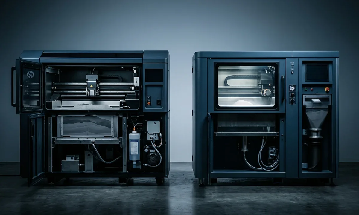
HP built Multi Jet Fusion around a powder-bed process that spreads thin Nylon layers, usually at 80-micron micron resolution, across a heated build chamber. Instead of tracing geometry with a laser, the printer deposits two liquid agents through an inkjet array. A fusing agent absorbs infrared energy where the part should solidify. A detailing agent cools the surrounding edges to sharpen corners and reduce thermal bleed.
Each layer forms in a single pass, which explains why MJF print time changes less dramatically as the build volume fills with more components. Dense part nesting helps. The surrounding powder supports overhangs naturally, so designers rarely need support structures or aggressive draft angle planning. After printing, operators leave the build unit to cool for several hours before unpacking and bead blasting the parts.
Most MJF components leave the machine in dark gray or black because the fusing chemistry carbonizes during exposure to infrared heat. Dyeing remains common for production work, especially in consumer products where surface consistency matters.
2MJF Material Options and Mechanical Properties
PA12 dominates commercial MJF production because it balances stiffness, chemical resistance, and dimensional stability. PA11 offers higher ductility and better impact resistance. TPU handles flexible geometries such as seals and protective housings. Glass-filled PA12 increases rigidity but sacrifices some elongation under load.
Mechanical performance stays relatively isotropic compared with many additive processes. Layers bond evenly because the entire powder bed heats uniformly during Elective Fusion. Surface texture also arrives smoother than most SLS parts, though not injection-mold smooth straight off the machine.

3MJF Speed, Nesting, and Cost at Scale
Production economics favor MJF once you batch dozens or hundreds of parts into one build. High nesting density spreads machine time across more components, lowering cost per unit and shortening overall print time for repeat jobs.
How Selective Laser Sintering Works
1The SLS Laser Sintering Mechanism
Selective Laser Sintering uses a high-powered CO2 laser to fuse powdered polymer layer by layer inside a heated chamber. A recoater spreads fresh powder across the bed, then the laser scans only the geometry required for that slice of the model. Unfused powder stays in place and supports the part during printing, which allows complex internal channels, snap fits, and lattice structures without separate support material.
Thermal management drives most of the process stability. If chamber temperatures fluctuate too aggressively, large flat sections can curl or shrink unevenly. Experienced operators compensate through orientation strategy, controlled cooling cycles, and careful part nesting. SLS systems also generate a visibly grainier texture than MJF because partially sintered particles remain attached to the surface after unpacking.
2SLS Materials: Broader Range Than MJF
Material flexibility remains one of SLS's strongest advantages. Standard Nylon grades such as PA12 and PA11 still dominate production, but open-material systems can process polypropylene, flexible TPE blends, carbon-filled composites, and high-temperature polymers like PEEK. Binder Jetting competes in some production environments, especially for metal applications, though it follows a different consolidation process entirely.
That wider polymer ecosystem matters for engineers chasing chemical resistance, elevated heat tolerance, or unusual flexibility targets. Some aerospace suppliers also prefer SLS because validated specialty powders entered the market years before equivalent MJF options appeared.
3SLS Machine Ecosystem and Market Availability
EOS, 3D Systems, and 3NTR established the industrial SLS market long before compact systems appeared. Smaller platforms from Formlabs, Sintratec, and Sinterit lowered entry costs for professional shops, universities, and advanced prototyping teams. Access improved quickly after that shift.
Open material policies influence ownership costs as well. Many SLS operators can source powder from multiple vendors instead of locking themselves into a single hardware ecosystem.
Head-to-Head: SLS vs MJF Compared
1Surface Finish and Dimensional Accuracy
Place an untreated MJF and SLS part side by side under direct light and the difference appears immediately. MJF surfaces look smoother and more uniform because the detailing agent sharpens edges while the fused powder consolidates more evenly across each layer. SLS parts usually show a slightly rough, sandy texture after depowdering, especially on curved surfaces and thin walls.
Dimensional accuracy overlaps more than many marketing sheets imply. Most production bureaus quote tolerances near ±0.3 mm plus 0.3% of nominal length for both technologies. Geometry still matters. Long flat parts can warp in either system if thermal gradients build unevenly during cooling.
The comparison below shows where each process separates in practical manufacturing work.
| Category | MJF | SLS |
|---|---|---|
| Fusion Method | Infrared fusing agents | CO2 laser sintering |
| Typical Surface Finish | Smooth, matte | Grainier, powder-like |
| Common Materials | PA12, PA11, TPU | PA12, PA11, PP, PEEK, TPE |
| Typical Layer Height | 80 microns | 100-120 microns |
| Support Structures | Not required | Not required |
| Color Output | Gray or black | Usually white or gray |
| Best Production Fit | Mid-to-high volume | Prototype to mid-volume |
| Typical Machine Cost | $250k-$600k | $20k-$500k+ |
2Part Strength, Isotropy, and Fatigue Performance
MJF parts often show more uniform Z-axis strength because the process heats each layer more consistently across the build area. Fatigue resistance also trends slightly better in repeated flex testing, at least in PA12 applications we have seen from production suppliers. Functional hinges and load-bearing brackets benefit from that consistency.
SLS still produces mechanically capable engineering parts. The gap narrows further with tuned process parameters and premium powders. High-temperature materials also shift the equation because MJF currently lacks equivalent support for several advanced polymers.
3Turnaround Speed and Production Volume Fit
MJF handles dense production builds efficiently because the machine processes entire layers at once. Fill the chamber with fifty housings instead of five and cycle time rises modestly rather than linearly.
SLS behaves differently. Laser path length increases with part count and nesting density, so production scaling slows earlier. Small batches remain economical, though. Prototype teams printing ten specialized components often prefer SLS because setup flexibility outweighs throughput limits.
4Total Cost per Part Across Volume Tiers
Volume changes the cost equation more than the process itself.
| Production Scenario | MJF Economics | SLS Economics |
|---|---|---|
| 1-10 parts | Higher setup burden | Usually lower cost |
| 50-500 parts | Strong cost efficiency | Competitive but slower |
| Large production batches | Often lowest unit cost | Less efficient scaling |
| Post-processing labor | Lower | Higher |
| Powder refresh cost | Moderate | Material-dependent |
| Typical service pricing | Higher minimum order | More flexible quoting |

When to Use MJF vs SLS
1Choose MJF When Production Volume and Consistency Matter
A consumer electronics enclosure printed once for fit validation creates a different manufacturing problem than 5,000 identical housings shipping every quarter. MJF handles the second scenario better. Repeatability stays tight across large nested builds, and the smoother as-printed finish reduces secondary finishing work.
Medical device suppliers often choose MJF for surgical guides, orthotic components, and compact production tooling because the process delivers consistent wall thickness and dependable mechanical properties. Watertight geometries also perform well after bead blasting and dye finishing.
Production throughput matters just as much. A service bureau can stack hundreds of small Nylon components in one MJF build without dramatically increasing cycle time. That economics profile explains why many contract manufacturers route end-use Nylon production toward HP systems once annual volume rises above several hundred units.
2Choose SLS for Material Diversity or Low-Volume Runs
SLS remains the more flexible process for engineering teams testing unusual polymers or building low-volume functional assemblies. Polypropylene, carbon-filled Nylon, and specialty elastomers appear far more frequently in SLS environments than MJF shops.
Short-run manufacturing also fits naturally into the SLS workflow. If you need twenty brackets in a high-temperature polymer, MJF may not even offer the material. Service access becomes easier as well because smaller SLS systems entered the market at lower investment thresholds.
Flexible components illustrate the difference clearly. Some TPE blends process more reliably in SLS platforms than current MJF alternatives, especially in thin-wall geometries.
3Hybrid Strategies: Using Both in One Workflow
Several manufacturers split development across both technologies. Early prototyping often starts on SLS because material experimentation happens faster and machine access costs less. Production then shifts to MJF after geometry stabilizes and demand forecasts justify higher-volume output.
The workflow mirrors traditional manufacturing logic. Prototype broadly first. Standardize later.

Costs, Availability, and the Vendor Landscape
1Service Bureau Pricing Benchmarks for Both Processes
Service pricing changes quickly based on geography, machine utilization, powder refresh ratios, and post-processing requirements, but several trends remain consistent. Small Nylon parts from established bureaus usually land between $0.40 and $0.90 per cm³ for SLS. MJF commonly ranges from $0.50 to $1.10 per cm³ because operators often target larger production orders.
Lead time affects pricing almost immediately. Standard delivery windows sit near three to seven business days for both technologies. Expedited orders can double the quote. Cosmetic finishing also pushes costs upward, especially vapor smoothing, dyeing, and precision machining after printing.
Part geometry changes economics more than many buyers expect. Dense nesting improves MJF pricing dramatically, while oversized hollow shells consume valuable thermal space without adding enough billable volume to offset machine time.
2In-House Systems: Investment and Operational Realities
Desktop-accessible SLS systems lowered the entry barrier for professional prototyping teams. A Formlabs Fuse 1+ package can start near $35,000 before ancillary equipment and ventilation upgrades. Industrial EOS systems still climb well past $250,000 depending on chamber size and powder handling automation.
MJF remains firmly positioned in industrial production. Full HP installations often exceed $300,000 before facility modifications, unpacking stations, and material management infrastructure enter the budget discussion.
Operating costs matter after purchase. Powder recycling rates, cooling delays, labor requirements, and environmental controls shape ROI more than headline machine pricing alone.
The MJF vs SLS Bottom Line
Most buyers reach the MJF versus SLS decision after narrowing the field to powder-bed Nylon manufacturing. The remaining question is not which process looks more advanced. The question is which workflow fits the production target, material requirement, and operating budget with the fewest compromises.
MJF generally delivers better throughput, smoother cosmetic surfaces, and stronger production economics once part volumes rise. Consumer electronics housings, medical production components, jigs, fixtures, and repeatable end-use Nylon parts fit naturally into the process. Mechanical consistency also trends slightly better across large batches.
SLS still holds critical advantages. Material diversity remains broader, machine access costs stay lower, and short-run flexibility works exceptionally well for prototyping or specialized engineering applications. Teams developing parts in polypropylene, high-temperature polymers, or flexible TPE blends often reach SLS first because the ecosystem supports more experimental workflows.
Use this framework if you are making a purchasing or outsourcing decision:
- Need high-volume PA12 production with repeatable cosmetic quality? Choose MJF.
- Need specialty polymers or low-volume engineering runs? Choose SLS.
- Building a prototype-heavy product pipeline? Start with SLS, then shift mature geometries to MJF.
- Running a small internal lab with limited capital? Compact SLS systems remain more accessible.
- Prioritizing production throughput above all else? MJF usually wins.
Technical communicator specialising in 3D printing workflows, covering the full content spectrum: foundational guides, step-by-step how-to tutorials, hands-on reviews, curated top picks, troubleshooting solutions, and industry news.